
.Shuttleworth LVG CVI
(this page still to be constructed)
![]()
![]()
![]()
![]()
![]()
L.V.G. - REPORT ON VISIT TO BRUSSELS (1968)
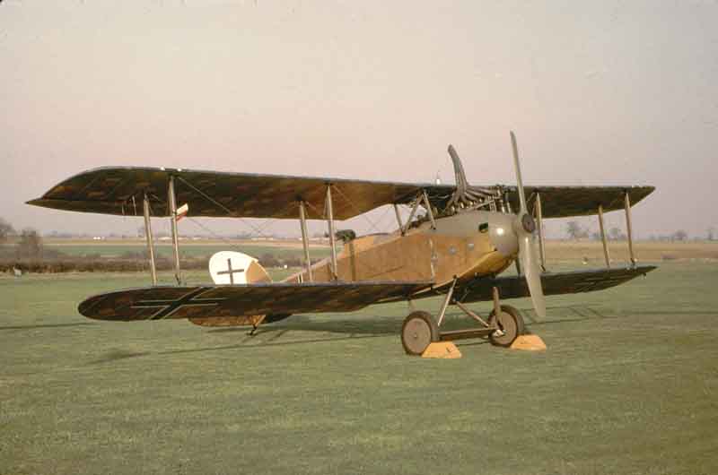
As far as it known there are only two LVG’s in existence; the one being rebuilt at Old Warden and that on display in the Brussels Army Museum. As the Brussels machine looked from photographs to be fairly complete, it was hoped that it would provide data on the parts missing from the Old Warden aircraft and also clear up one or two points about the finish.
Messrs. Brett and Tomlinson arranged to visit the Museum over two days, Tuesday and Wednesday 12th and 13th November 1968. It was planned to fly out on the 8.30 plane from Southend on Tuesday and leave Brussels at 5.00 p.m. on Wednesday. This would have given us Tuesday afternoon and most of Wednesday, the Museum opening hours being 10 to 12, 1.30 to 5.00. As it happened, fog at Ostende prevented take-off until 1.10 and consequently there was no time on Tuesday afternoon for other than introductions at the Museum. This seriously curtailed the time available, and although the Museum staff generously allowed us to start at 9.00 in the morning there were several minor points that we were unable to check. The greatest limitation was imposed by the height of the machine, which is suspended from the roof some 20ft. from the floor. It was necessary for the Museum staff to erect scaffolding to give us a working platform, and there was insufficient time to re-erect it other than in the original position. We choose the starboard side of the nose to give access to the inlet ducting for the carburettors, and were able to climb over the lower wing to get into the cockpit from this position.
General impressions were of the extreme helpfulness of the staff, who were most interested to learn of the Old Warden LVG: the rather sorry condition of most of the aircraft which appeared to have been put on display some 40 or 50 years ago and just left without further attention: and the correspondingly thick layer of sooty dust on all upper surfaces of the LVG. Although the machine was externally complete, internally there are a number of parts missing. The following outlines the aspects that we were interested in and our findings, with sundry comments. Finally I have listed at the end what I believe to be outstanding work, although this does not include normal routine tasks.
Overall Colour and Finish
The Brussels machine is widely reported as Werke No. 3141, which would make it an earlier machine than ours (4503). However, closer inspection revealed that the fuselage and cowlings actually carry the Werke No. 4981, the other No. being the only one visible from the ground; this is painted on the rudder and this I read as 5141 from a distance of 12 feet but at an oblique angle.
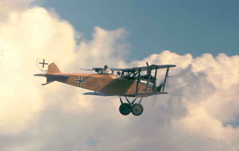
The fuselage ply covering of 4981 is varnished natural finish, the upper surfaces subject to the action of sunlight being a mahogany colour (which explains why the fuselage has been reported as being red), the under surfaces being nearer the colour of button polish or shellac. This supports the commonly held belief that LVG C V’s and VI’s (in common with most German aircraft with ply-covered fuselages) were normally plain varnish finish. (Ref: Summary of Air Intelligence, GHC, AEF, Sept. 1918. “LVG C VI Markings, wings and tail camouflaged but fuselage varnished yellow and rudder painted white”. Oct. 1918 “LVG C V have yellow bodies with camouflaged wings”. Ref. also translated German official document from Inspector of Aircraft Factories dated 20/9/18, to “All firms”…. “Camouflage of frontline A/C….. the bright yellow or likewise bright colour of those parts of the fuselage which are made of plywood has an adverse effect…..”). As the Brussels A/C has a later Werke No. it indicates that 4503 was almost certainly finished in the same manner. In most photographs, the varnish can be seen to have a very high gloss finish, almost as if French polished.
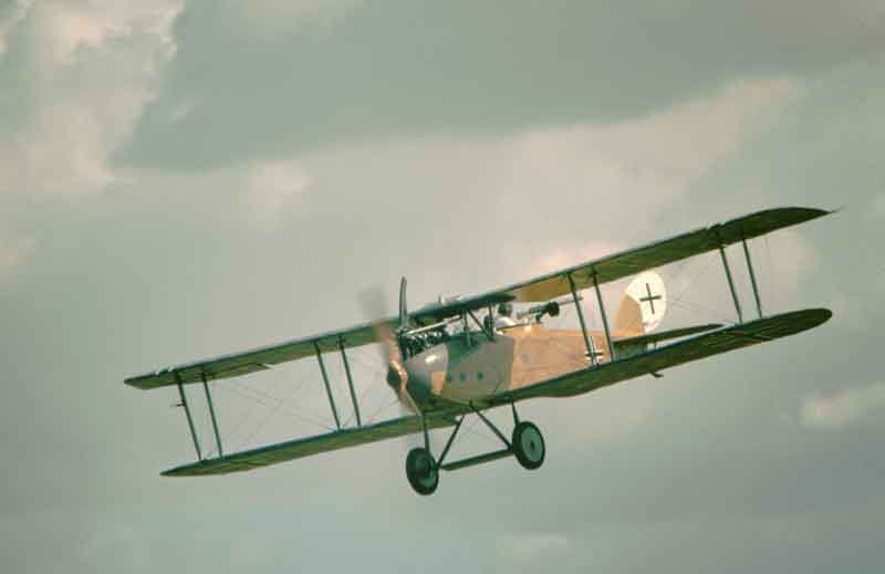
Cowlings, metal panels, centre-section and all wings and U/C struts are dark green on 4981, but flakes of paint from the engine cowling indicate that the first coats were a light green-grey. The cowlings have certainly been over-painted, because different shades of at least two coats are visible. The struts appear to have been overpainted after leaving the factory as some metal fittings normally painted black were overpainted. Most photographs of factory-fresh machines show a lightish shade of paint on all those parts, with the black fittings contrasting strongly – the yellow varnish usually shows up darker than the paint because the type of photographic film commonly used at that time showed yellow as a very dark colour. The light green paint has a tonal value corresponding roughly to a light brown-grey found under the thick top layers of Brunswick green paint on several panels on the Old Warden machine. The Germans used the paint very sparingly in 1918 and it is fairly safe to assume that the under layers are the original top finish. On this score it is interesting to note that the Munsell colour Ref. (1OYR4.5/2) of the under layers on 4503 is very close to the colour paint found on the Albatross DV in the Australian War Museum, which also has a yellow varnished fuselage. The metal panels on the lower port wing fitted to 4503 have a first coat of dark khaki-green but this wing was not the original one as it had a different Werke No. The only other metal panels on the wings have no original paint remaining. On this basis I would recommend that all metal panels, struts and centre section are finished in the original brown grey found on the fuselage panels.
Fabric.
The Brussels machine has “undersurface” 5-colour printed fabric on all undersurfaces. The top surface of the lower starboard wing was not as previously reported painted grey, but covered with topsurfaces 4-colour printed fabric, which was coated with a thick layer of grey dust. All wings were covered top and bottom with printed fabric. Rib tapes are of mixed colours, the tail unit having light colour (very pale blue?) tapes, and the wings having tapes cut from uppersurfaces printed fabric. Most photographs of LVG C VIs show light colour tapes throughout and I would recommend that we use light blue tapes on all surfaces. Rib tapes are approximately 1-1/8” (30 mm) wide with straight cut edges. Leading and trailing edges are covered with tapes cut from uppersurface fabric, the width varying to suit the edge radius. The fabric is applied chord-wise, machine stitched edge-to-edge; with two rows of stitching approximately 1/8” apart visible at the join. There appeared to be about ½” overlap at the join. The fabric is 50” wide between rows of stitching and the basic pattern is 18” long. The undersurface colours match reasonably well the colours we have used on our fabric, allowing for fading, dirt and the browning effect of old dope. It was not possible to check our uppersurface colours as no 5-colour pattern was visible.
Stitching was exceedingly neatly done with a close stitch. I could not tell how the trailing edges were stitched as the join was covered with tape.
Markings. The only marking visible were straight-sided “Balkan” crosses on the fuselage sides (outlined in white) and on the white-painted rudder. The crosses under the wing had been painted over and the upper surfaces of the wings were so thickly coated with dust that no crosses were visible. The machine has been quoted as having been used by a training unit and carries a fuselage Unit marking of a black band immediately in front the cross with a red (varnish?) circle on the black band. The band covers up the Air Force serial No. , although this has been quoted (mistakenly I believe) as 3141/18. The only other markings that I could see were those referring to the weights, which are as painted on 4503 in a similar style but further forward on the fuselage. I could not see “lift” instructions by the handholds in the rear of the fuselage, nor have I found any LVG photographs on which these can be seen, although it was not uncommon to find these markings on some German aircraft.
As I was unable to get up to the tail of the machine I was unable to look for Serial Nos. or “house” markings on the tailplane and elevator, which of course were so covered with dust that nothing was visible on top. There was no house mark in the usual position on the fin or rudder and I could not see one anywhere else.
In the absence of any subsequent information I would suggest that we use blue and yellow for the house badge (blue outline, yellow centre): this is a verbal description given to me but not supported by any positive evidence except that these colours do fit the tonal values seen on black and white photographs.
One other item which is missing from the Brussels machine is the manufacturer’s data card which was normally mounted externally, on the front port side of the fuselage. This is visible in all photographs but no information has yet come to hand as to what was on the card. It is believed to be rigging and CG dates; enquiries are still under way for this.
We still cannot absolutely certain of the Air Force Serial No. for 4503, but knowing that these numbers were allocated in blocks, it is fair to assume that the gap between Werke No. and Serial Nos. on other aircraft whose numbers are close to 4503 can also be applied to 4503. E.g. an aircraft with Werke No. 4586 has Serial No. 6731/18, a gap of 3045. This Werke No. is very close and if 3045 is added to 4503, it gives a Serial No. 7458/18, which has a 50/50 chance of being the correct one. The nearest combination I know of is Werke No. 4701, Serial No. 7744/18, given a gap of 3043, a difference of only 2 in 200.
It was common practice for German aircraft to have vertical and/or horizontal datum lines painted in red on the fuselage. The Brussels machine showed no evidence of such having been applied, but I have a photograph of a factory line-up in which both vertical and horizontal lines can be seen. If required, I can determine sizes and positions of these and will also seek further confirmation.
Tailplanes.
The tailplanes appeared to have been covered before fitting to the air-craft; this also being standard on the CVs. Photographs of completed machines dismantled for crating or transport show the covered tailplanes removed from the fuselage. The main spar appears to be of box section with a removable inner spar which is passed through the fuselage. Each half tailplane has a rear spar, to which appears to be bolted externally, a one-piece spar connecting both tailplanes. Presumably, the elevator hinge fitting also bolt the external spar to the tailplanes (this seems to be used also on Rumpler tailplanes). All this suggests that the tailplane on 4503 is not original as I believe it has a one-piece conventional spar. This is supported by the fact that the rudder and elevator are also not original, these being normally of metal construction.
Rudder.
The Brussels machine has a white-painted rudder with Werke No. and black cross. Only one rib tape is applied to the rudder and the control horns are not braced. The wooden rudder made by the RAF for 4503 has braced horns and incidentally is of the wrong outline shape. Would it be possible to have a metal rudder of the correct outline made 4503? I could produce a dimensional outline drawing (not the original alas).
Struts.
The new struts and fitting of 4503 are very good replicas of those on the Brussels aircraft, and only the extremely knowledgeable will be able to detect that they are not original. The tape wrappings are approximately 1 and ¼” wide with about 7 turns at three places on each strut. It was not possible to see any markings on the struts, which supports the theory that these were overpainted in the field.
Undercarriage.
4981 is fitted with solid wooden wheels which the Germans used in lieu of normal wheels for ground transport purposes, to save wear on the rubber tyres. These wheels are of 30” diameter overall; this corresponds to the 32” (810 mm) tyred wheels, allowing 1” compression of the tyre when loaded. The centre axle fairing is 7 3/4” wide in section, and the spreader bar is 1-5/8”dia. and 4’ 9 ½” between centres. Wire restraining hoops are fitted above the axle at each side to restrict upward travel of the axle.
Access to the tailskid springing is via a hinged panel in the stbd. side of the fuselage immediately under the tailplane main spar.
Radiator.
As with all other C VI’s in photographs showing details of the radiator, the Brussels a/c has both inlet and outlet hose connections on the port side. There is a drain tap on the starboard side with a drain pipe strapped to the stbd. diagonal c/section strut: the pipe is routed inside the cockpit to vent on the underside of the fuselage. An overflow pipe runs from near the return outlet round the stbd. and front edges, and probably enters the vertical filler and header tank. The latter is much higher than that on 4503 which has obviously been made up without a pattern to refer to. The most serious fault on our radiator, however, is that the return pipe is on the stbd. instead of the port side. The return pipe on 4981 crosses diagonally form port to stbd, and of the stbd. side incorporates a tapping in which was probably mounted a vertical water temp. gauge. This can be seen but not positively identified in contemporary photographs. The return pipe appears to be an alloy casting connected to the radiator and water pump by short lengths of rubber hose. It should be possible to locate the return outlet on the port side of 4503’s radiator and to use suitable car radiator hose with outlet toppings for a temp. gauge. The radiator is painted aluminium top and bottom hear-resisting paint?).
The radiator shutters are missing on 4981, but the rear bracket and attachment points were still in place. It should be possible to draw for manufacture a suitable shutter mechanism from these parts dimension and photographic evidence.
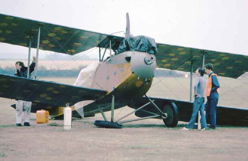
Engine installation.
Removal of the stbd. engine cowling of 4981 showed that the engine is a late model with a generator mounted on the stbd. side immediately behind the rear carburettor duct and no evidence of one having been fitted. The forward duct is secured by screws to the engine mounting platform and it is fair to assume that a duct, if fitted to the rear intake, would be secured in the same manner; there is however no sign of screwholes by which it might have been secured. On closer inspection, it was felt that the rear outlet of the forward duct, in being tapered, would produce a jet effect which could be sufficient to provide the required feed to the mouth of the rear carburettor intake. It seems reasonable to try running the engine without a rear duct fitted before trying to design and make one.
The positions of all vents and drain pipes were noted. The half-compression cam lever at the rear of the engine was disconnected, and as on our engine appeared to have no effect when rotated by hand. However, a hefty handle on the port side of the cockpit which appeared to be disconnected in the engine bay may have been the means of operating the lever – it was certainly big enough.
The cooling air inlet duct for the crankcase has an oval intake projecting slightly from the underside of the nose; the corresponding outlet duct as fitted on our engine has no rearward extension, a single large outlet louver serving to vent at least some of the used cooling air. The remainder presumably exhausted via the front bulkhead into the cockpit providing a heating effect for the pilot’s feet? Neither intake nor outlet louvers are at present fitted to 4503 but drawings are in hand.
A circular inlet/outlet? vent at the rear of the stbd. engine cowl, visible in all photographs, is not fitted to the Brussels machine; the cowling has a separate panel to the rear of the front strut to enable the cowling to be removed when the front gun is in position and this panel normally fits round the circular vent. On 4981 this panel had no cutout for the vent so the a/c was obviously flown without it; as it is not essential for flight, and research has so far not revealed its purpose, I would suggest that we do likewise with 4503. My guess is that the pipe is to convey cooling air through the cooling duct at the top rear of the crankcase but I can find no positive evidence of this.
Access to the sump connections and oil filter are made via a hinged louvred panel in the underside of the fuselage, the hole being rather larger and of a different shape to that on 4503.
Engine Cowlings.
Both stbd. and port engine cowlings are fitted with louvred access panels as on the fuselage sides. Construction of 4 such panels (plus two others required elsewhere on the fuselage) is almost complete. Full dimensions of the starboard cowling, complete with gun through, and of the rear detachable panel are now available, and the port cowling is similar, less gun through and detachable panel.
A separate small central panel is normally fitted between the rear of the two side panels, but was missing on the Brussels machine. This should be a simple matter to produce as it will be of single curvature and has only to overlap the side panels and the front fuselage bulkhead. A cowl fitted round the front and sides of the upper part of the cylinders is fitted to 4981, and dimensions have been taken; however, it appeared to be standard practice to remove this in the field and it would not be necessary to fit this cowl, especially as it might increase the engine cooling problem.
Oil tank and lines.
The oil tank and lines on 4981 appear to be identical to those on 4503. Access to the oil filler cap is via a hinged louvred panel on the starboard cowling. The oil pressure line from the engine to the oil pressure gauge incorporates a T-connection and drain pipe in the pilot’s cockpit, the drain venting under the stbd. side of the cockpit.
Fuel tank and lines.
The gravity wing tank has two connections, one to the three-way cock on the dashboard and the other to a connection on top of the left side of the main tank and thence to a pump. On the Brussels machine, the wing tank filler which normally protruded through the upper surface of the wing was covered over with fabric. Evidently this tank was normally only filled by the handpump from the main tank.
The main fuel tank was inserted through the top of the fuselage, the top decking over the pilot’s cockpit being removable for this purpose. The main tank has a small conical sump and drain cock at the centre of the lower rear face, the drain cock protruding through a hinged panel on the underside of the fuselage. The tank is secured by two straps which also appear to secure the pilot’s seat to the top of the tank. Alongside the port side of the seat are, from the rear, a 3-way union, which I believe to be a hand pressure pump and the fuel filler. The union is connected to a petrol/time Maximall gauge mounted …
… the side control panel. A pipe connects the union also to the 3-way cock (marked ZU, HAUPT TANK, FALLTANK: off, main tank, gravity tank), the third union being disconnected on the Brussels machine. Access to the filler is through a hinged panel on the side (port) of the fuselage and a circular hole in the side control panel.
The control panel on 4503 looks to be completely original but the Maximall gauge is missing. The hinged panel under the fuselage is being drawn and manufacture of the hinged panel on the side of the fuselage is almost complete.
Instruments.
Unfortunately all the instruments on the Brussels machine are missing. However, a rev. counter similar to the distinctive type normally fitted was on show in a glass case and details were noted. The rev. counter and drive are both anti-clockwise, the drive being a ½ engine speed. The rev. counter is mounted on top of the cockpit coaming behind the windscreen and immediately in front of the pilot. Oil pressure and petrol pressure gauges were mounted on the dashboard.
There was provision for a third instrument between the two pressure gauges, which may have been a remote reading water temperature gauge (Fern thermometer). No other instruments appear to have been fitted as standard, although it was not uncommon to fit an anemometer type a.s.i. to the starboard centre-section strut. An adjustable mirror mounting arm is fitted to the Brussels aircraft and the port side of the front cockpit coaming. This appears to be a standard “extra” as the museum has a complete mirror and arm assembly in a showcase.
Seats.
The rear cockpit has a plain fabric-covered and upholstered bench seat resting on the central members running along each side of the cockpits. There is no guarantee that this was an original seat but it would be convenient to use when operating the camera, and not be in the way when operating the rear gun. The seat is 10 ½” wide and extends across the whole width of the fuselage.
The pilot’s seat is a large bucket type, consisting of a ply base with a one-piece wrap-round ply back and sides. The ply is approximately ¼” thickness and has many lightening holes. The back and sides are comfortably upholstered, the sides being high enough to serve as armrests! A removable seat squab was used but is missing from the Brussels machine. The seat is strong and comfortable and incidentally the seating position provides a magnificent view over the nose despite the conglomeration of cooling hoses, bracing wires and engine top hamper.
Cockpits.
No fittings not already described remain in 4981 except a fuse (?) box on the forward right-hand side of the pilot’s cockpit. The bulkhead between the two cockpits is filled in with thin ply. An instruction (?) plate of some sort had once been fitted to the control panel, and I would guess was a diagram of the fuel system as such were sometimes fitted to aircraft with Benz engines and fuel systems. In the rear cockpit floor was a 10” square camera hatch and a 5 ¼” dia. serial hole. The camera hatch should have been provided with an external sliding cover; photographs suggest that this slid between external fore-and-aft runners. Dimensions and locations of these holes are available.
The edge of the cockpit is provided with leather-faced padding of approx. 3” thickness at the front tapering to about 1 ½” at sides and rear. Controls on 4981 are identical to those on 4503 except that the control column looking device is missing on 4981.
Windscreen.
The windscreen on 4981 has been broken and very little remains. However, sufficient is left to be able to draw the screen and mounting. It is a plain curved screen of about 3/32” thick celluloid (now considerably yellowed).
Armament.
Both fixed and free guns are fitted on the Brussels LVG. The front gun is a standard Spandau aircooled type, mounted on the two bulkheads immediately in front of the pilot, in cut-outs offset to starboard. The barrel and jacket project into a trough in the cowling and the cockpit coaming is cut away round the breech to accommodate the spent cartridge collecter chute and to allow the pilot to operate the cocking handle etc. A rearward extension of the cocking handle protrudes into the cockpit, but this looks to be a “home-made” device. A housing for the ammunition tank is mounted on the rear of the engine bulkhead on 4981, but it is not clear how the spent cartridges were collected. There is room for a box or bag between the ammunition tank housing and fuselage side but no visible means of support for a box. I could not find the interrupter gear drive connection for the gun. The standard ring and backsight are fitted and it was notable that although the gun looks to be well out of the way, little head and shoulder movement was required to be able to look along the sights.
The rear gun is a 1918 pattern air-cooled Parabellum with rifle-type butt and side-mounted cartridge belt drum. Details of the mounting are available and it was noted that at least eight other Parabellum guns were on show in different parts of the Museum – perhaps they could be induced to loan us one if that half-promised by the Imperial War Museum fails to materialise? The gun ring is identical to that on 4503, but with the addition of a pair of rollers the object of which is clear.
Propeller.
The propeller on 4981 is very similar in shape to the one obtained from the I.W.M. except that the hub like that on the airscrew on 4503. Diameter is 3.0 metres and pitch 1.85 metres. Propeller finish is plain varnish which shows up the laminations.
Fuselage.
Construction and number of formers is as on 4503. Pine ply panels are overlapped front to rear, with only slight chamfering of the overlap. The longitudinal edge joints are sealed with 1 ½” wide tape of very thick material (first impression was that the material used was thin metal). The lateral joints were not sealed with tape.
Apart from two hinged panels not present on 4503 (one for fuel filler, the other for access to the tailskid springs), two handholds are formed in the underside of the fuselage, one each side just forward of the tailplane leading edge. Drainholes are provided in the underskinning on the fuselage centreline, aft of each former behind the cockpit and forward of the formers in front of the cockpit.
Bracing.
Bracing wires were apparently not painted on leaving the factory although some photographs suggest this may have been done in the field. It was difficult to be certain whether the dull finish on the Brussels machine is a thin coat of paint or grime. At all points were diagonal bracing wires crossed, they were secured together by clips, the dimensions of which are available.
M. Brett
| LVG CVI | Halberstadt CV | 216 diary | contact me | artwork | links | Home | top |
|---|